Design Guide — Sheet Metal Bending
This guide presents the Design for Manufacturing (DFM) rules to follow when designing bent sheet metal parts fabricated by Laseo. Following these rules ensures part feasibility, minimizes lead times, and guarantees dimensional quality. Our app automatically checks most of these rules at design time — this guide helps you get it right the first time.
Process: air bending on a CNC press brake. The bend radius is determined by the material, the thickness and the tooling. Custom radii are not offered. The bending service is presented in detail on the bending service page.
Skip the math: the app checks these rules for you.
Draw or upload your flat part, add bends, and see minimum flanges, hole-to-bend warnings and the price instantly. No account needed.
1. Sheet metal bending terminology
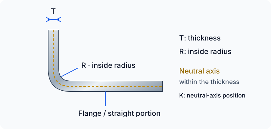
Before designing a bent part, it's essential to understand the fundamental terms: inside radius (R), thickness (T) and angle (θ) define the anatomy of every bend.
| Term | Definition |
|---|---|
| Bend angle (θ) | Angle between the two faces after bending |
| Inside radius (R) | Radius of curvature of the inside surface of the bend |
| Thickness (T) | Sheet metal thickness |
| K-factor (K) | Neutral axis position through the thickness: K = t/T |
| Flange | Flat portion between the part edge and the start of the bend |
| Bend allowance (BA) | Arc length of the neutral axis in the bend zone |
| Bend deduction (BD) | Reduction applied to the flat pattern for each bend |
| Bend line | Line on the flat pattern where the bend occurs |
| Die | Bottom V-shaped tool — its width drives several constraints |
| Bend relief | Cutout at the ends of a bend line to prevent tearing |
2. What is the bend radius?
The inside bend radius is fixed for each material/thickness combination. It depends on the tooling (punch and die) and cannot be customized. Check the "Inside radius" column in the master table for your material's exact radius.
In practice, radii range from 0.024″ for thin sheet to 0.346″ for 1/4″ stainless. Design your 3D models with these radii so the computed flat pattern matches the manufactured part.
3. What is the minimum flange length?
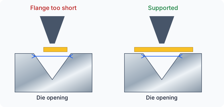
The flange length is the distance between the part edge and the start of the bend zone. If the flange is too short, the sheet slips in the die and the bend won't form correctly — the flange deforms instead of bending.
Minimum flange ≈ max(2 × T, T + R)
Exact values per material and thickness (0.200″ to 1.155″) are in the "Min flange" column of the master table. The app automatically blocks any bend whose flange would be too short.
4. How far from a bend should holes and cutouts be?
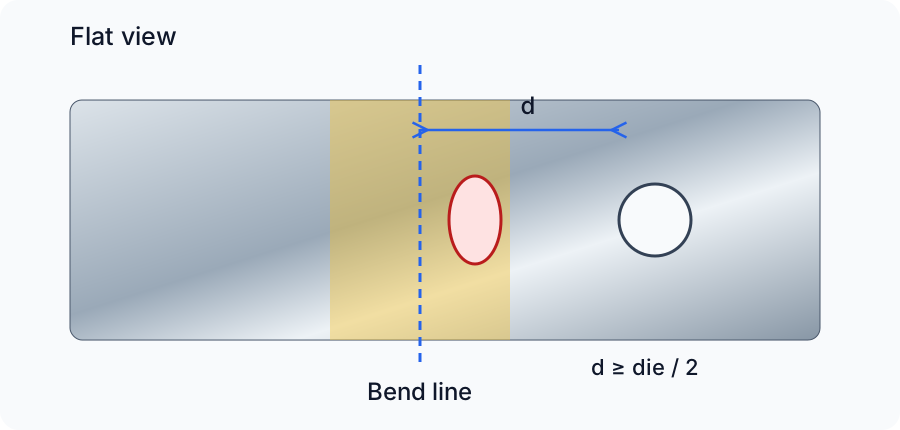
Holes, slots, engravings and any other cut feature must be far enough from the bend line. A feature that is too close sits in the die contact zone and will be distorted during bending.
Minimum distance = die width ÷ 2
| Die width | Minimum distance | Metric |
|---|---|---|
| 0.472″ | 0.236″ | 6.0 mm |
| 0.630″ | 0.315″ | 8.0 mm |
| 0.984″ | 0.492″ | 12.5 mm |
| 1.575″ | 0.788″ | 20.0 mm |
Tapping and hardware insertion are done before bending. A distorted hole renders threads unusable — respect this distance for any tapped hole or hardware location.
5. What is the minimum distance between two bends?
For two parallel bends, the minimum distance between bend lines depends on the bend angle. Bends that are too close make the die contact zones overlap, which causes metal puckering.
Parallel bends
| Bend angle | Minimum distance |
|---|---|
| 5°–45° | Material joggle spec (see below) |
| 46°–90° | 2 × minimum flange |
| 91°–130° | Acute angle spec — checked case by case by the app |
Joggles (close Z-bends, opposite directions)
| Die width | Minimum joggle distance |
|---|---|
| 0.472″ | 0.700″ |
| 0.630″ | 0.900″ |
| 0.984″ | 1.200″ |
| 1.575″ | 1.500″ |
6. What bend angles are possible?
| Parameter | Value |
|---|---|
| Minimum angle | 5° |
| Maximum angle (standard) | 130° |
| Thick stock (≥ 3/16″) | 90° max |
The exact range per material/thickness is shown in the app when you add the bend.
Angular tolerances
| Condition | Tolerance |
|---|---|
| Sheet metal, bend ≤ 24″ | ±1° |
| Sheet metal, bend > 24″ | ±2° |
7. When is a bend relief needed?
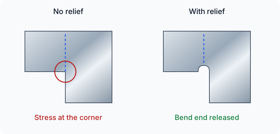
A bend relief is a small cutout at each end of a bend line that prevents the sheet from tearing or deforming when the bend runs into solid material.
- Recommended for thicknesses ≥ 3/16″ (0.187″)
- Recommended wherever a bend line meets an inside edge
Minimum dimensions per material are in the "Relief" column of the master table. When in doubt, this conservative rule works in all cases:
Depth ≥ R + T + 0.020″ · Width ≥ 50% × T
8. How do I calculate bend allowance and the flat pattern?
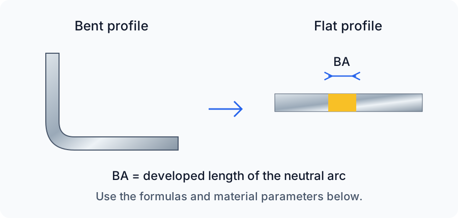
During bending, the sheet stretches in the bend zone. The flat pattern must account for that deformation through the bend allowance (BA) or the bend deduction (BD). STEP import is planned for early October 2026. For now, prepare your flat 2D drawing using the parameters below.
BA = θ × (R + K × T) // θ in radians
BD = 2 × (R + T) × tan(θ/2) − BA
OSSB = (R + T) × tan(θ/2)
Lflat = Lflange 1 + Lflange 2 + BA
Example — Aluminum 5052-H32 14G, 90° bend
T = 0.064″ R = 0.047″ K = 0.459 θ = 90° = π/2 rad
BA = (π/2) × (0.047 + 0.459 × 0.064) = 0.120″
BD = 2 × (0.047 + 0.064) × tan(45°) − 0.120 = 0.102″
The "BD @ 90°" column in the master table gives the precomputed deduction for each material/thickness — the value to subtract per 90° bend if you're building your flat pattern by hand.
9. What tolerances should I expect?
Bending — ±0.015″ per bend, cumulative
| Number of bends | Tolerance |
|---|---|
| 1 | ±0.015″ |
| 2 | ±0.030″ |
| 3 | ±0.045″ |
| 4 | ±0.060″ |
| 5+ | ±0.015″ × n |
Cutting
±0.005″ (±0.13 mm) on laser-cut profiles.
Design tip: dimension critical features from the same bend rather than chaining across several bends — bending tolerances stack up.
10. Part size constraints
| Parameter | Value | Metric |
|---|---|---|
| Minimum part size | 0.375″ × 1.500″ | 9.5 × 38 mm |
| Maximum part size | 30″ × 44″ | 762 × 1118 mm |
| Maximum bend length | 16″ to 44″ depending on material | 406 to 1118 mm |
| Maximum bends | 12 per part | — |
11. U-channels: what base-to-flange ratio?
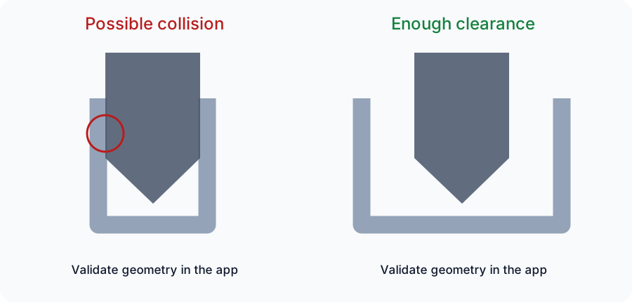
For a U-profile, the base (the panel between the two bends) must be wide enough relative to the flange height, otherwise the part collides with the tooling and cannot be air-bent.
| Condition | Minimum ratio |
|---|---|
| Standard | Base ≥ 2 × flange height |
| Thin sheet (≤ 0.135″) | 1:1 accepted if flanges ≤ 3.00″ and base ≥ 1.00″ |
12. Bending specifications per material
The master table below gives, for every bendable material and thickness at Laseo: the V-die, the inside radius, the K-factor, the minimum flange, the relief depth and the 90° bend deduction. All values in inches.
| Material | T (in) | V-die | Inside radius | K-factor | Min flange | Relief depth | BD @ 90° |
|---|---|---|---|---|---|---|---|
| Aluminum | |||||||
| 3003-H14 — 22G | 0.025 | — | 0.039 | 0.380 | 0.200 | 0.038 | 0.064 |
| 5052-H32 — 18G | 0.040 | 0.315 | 0.039 | 0.330 | 0.200 | 0.060 | 0.076 |
| 5052-H32 — 14G | 0.064 | 0.472 | 0.047 | 0.459 | 0.285 | 0.096 | 0.102 |
| 5052-H32 — 12G | 0.081 | 0.630 | 0.047 | 0.371 | 0.382 | 0.122 | 0.135 |
| 5052-H32 — 11G | 0.091 | 0.630 | 0.047 | 0.400 | 0.382 | 0.137 | 0.145 |
| 5052-H32 — 10G | 0.102 | 0.945 | 0.063 | 0.425 | 0.568 | 0.153 | 0.163 |
| 5052-H32 — 8G | 0.129 | 0.945 | 0.157 | 0.420 | 0.568 | 0.194 | 0.242 |
| 5052-H32 — 3/16″ | 0.188 | 1.575 | 0.157 | 0.418 | 1.000 | 0.282 | 0.320 |
| 5052-H32 — 1/4″ | 0.250 | 1.969 | 0.312 | 0.392 | 1.155 | 0.375 | 0.480 |
| Mild steel (hot rolled) | |||||||
| HR steel — 22G | 0.030 | 0.315 | 0.055 | 0.289 | 0.200 | 0.045 | 0.070 |
| HR steel — 18G | 0.048 | 0.394 | 0.067 | 0.262 | 0.245 | 0.072 | 0.105 |
| HR steel — 16G | 0.060 | 0.472 | 0.075 | 0.288 | 0.285 | 0.090 | 0.125 |
| HR steel — 14G | 0.075 | 0.630 | 0.102 | 0.236 | 0.382 | 0.113 | 0.166 |
| HR steel — 12G | 0.105 | 0.945 | 0.146 | 0.295 | 0.568 | 0.158 | 0.224 |
| HR steel — 11G | 0.120 | 0.945 | 0.125 | 0.385 | 0.568 | 0.180 | 0.221 |
| HR steel — 10G | 0.135 | 0.945 | 0.125 | 0.418 | 0.568 | 0.203 | 0.235 |
| HR steel — 3/16″ | 0.188 | 1.575 | 0.217 | 0.431 | 1.000 | 0.282 | 0.342 |
| HR steel — 1/4″ | 0.250 | 1.969 | 0.272 | 0.379 | 1.155 | 0.375 | 0.468 |
| Galvanized steel G90 | |||||||
| G90 — 24G | 0.028 | 0.315 | 0.055 | 0.218 | 0.200 | 0.042 | 0.070 |
| G90 — 22G | 0.034 | 0.315 | 0.055 | 0.330 | 0.200 | 0.051 | 0.070 |
| G90 — 18G | 0.052 | 0.394 | 0.067 | 0.340 | 0.245 | 0.078 | 0.105 |
| G90 — 16G | 0.064 | 0.472 | 0.075 | 0.350 | 0.285 | 0.096 | 0.125 |
| G90 — 14G | 0.079 | 0.630 | 0.102 | 0.288 | 0.382 | 0.119 | 0.166 |
| G90 — 12G | 0.108 | 0.945 | 0.146 | 0.322 | 0.568 | 0.162 | 0.224 |
| Stainless steel 304 | |||||||
| 304 #2B — 22G | 0.031 | 0.394 | 0.085 | 0.277 | 0.245 | 0.047 | 0.085 |
| 304 #2B — 18G | 0.050 | 0.472 | 0.094 | 0.437 | 0.285 | 0.075 | 0.106 |
| 304 #2B — 16G / 1/16″ | 0.063 | 0.630 | 0.141 | 0.480 | 0.382 | 0.095 | 0.139 |
| 304 #2B — 14G | 0.078 | 0.630 | 0.117 | 0.361 | 0.382 | 0.117 | 0.162 |
| 304 #2B — 12G | 0.109 | 0.945 | 0.203 | 0.445 | 0.568 | 0.164 | 0.229 |
| 304 #2B — 11G | 0.125 | 0.945 | 0.188 | 0.462 | 0.568 | 0.188 | 0.240 |
| 304 #2B — 7G | 0.188 | 1.575 | 0.250 | 0.357 | 1.000 | 0.282 | 0.378 |
| 304 #1 — 1/4″ | 0.250 | 1.969 | 0.346 | 0.365 | 1.155 | 0.375 | 0.505 |
| Stainless steel 316 | |||||||
| 316 #2B — 1/16″ | 0.063 | 0.630 | 0.141 | 0.480 | 0.382 | 0.095 | 0.139 |
| 316 #2B — 1/8″ | 0.125 | 0.945 | 0.188 | 0.462 | 0.568 | 0.188 | 0.240 |
| 316 #1 — 3/16″ | 0.188 | 1.575 | 0.250 | 0.357 | 1.000 | 0.282 | 0.378 |
| 316 #1 — 1/4″ | 0.250 | 1.969 | 0.346 | 0.365 | 1.155 | 0.375 | 0.505 |
| Brass 260 (cartridge) | |||||||
| Brass 260 — 18G | 0.040 | 0.320 | 0.039 | 0.370 | 0.200 | 0.060 | 0.076 |
| Brass 260 — 14G | 0.064 | 0.512 | 0.047 | 0.330 | 0.285 | 0.096 | 0.102 |
| Brass 260 — 8G | 0.129 | 1.032 | 0.157 | 0.300 | 0.568 | 0.194 | 0.242 |
| Brass 260 — 3/16″ | 0.188 | 1.504 | 0.157 | 0.380 | 1.000 | 0.282 | 0.320 |
| Brass 260 — 1/4″ | 0.250 | 2.000 | 0.312 | 0.330 | 1.155 | 0.375 | 0.480 |
| Copper 110 ETP (half hard) | |||||||
| Copper 110 — 19G | 0.043 | 0.344 | 0.039 | 0.390 | 0.200 | 0.065 | 0.064 |
| Copper 110 — 16G | 0.062 | 0.496 | 0.047 | 0.330 | 0.285 | 0.093 | 0.102 |
| Copper 110 — 10G | 0.134 | 1.072 | 0.063 | 0.340 | 0.568 | 0.201 | 0.163 |
13. The 6 most common design mistakes
1. Holes too close to the bend
Respect the minimum distance Die ÷ 2. Holes inside the die zone will be distorted.
2. Flange too short
The sheet slips in the die and the bend deforms. Meet the minimum flange from the material table.
3. No bend relief on thick material
Tearing risk at the ends of the bend. Add reliefs of depth R + T + 0.020″.
4. Bends too close together
Die zones overlap and pucker the metal. Keep 2 × minimum flange between parallel bends.
5. Channel too narrow
The base-to-flange ratio must be ≥ 2:1, or the part hits the tooling.
6. Forgetting the bend deduction
Without BD, the finished part will be larger than expected. Use the section 8 formulas. STEP import is planned for early October 2026.
14. Quick reference
| Rule | Value / formula |
|---|---|
| Feature-to-bend distance | ≥ Die ÷ 2 |
| Minimum flange length | See material table (≈ max(2T, T+R)) |
| Distance between bends (46°–90°) | ≥ 2 × minimum flange |
| Angles | 5°–130° (standard), 90° max from 3/16″ |
| Per-bend tolerance | ±0.015″ cumulative |
| Cutting tolerance | ±0.005″ |
| Bend relief — depth | R + T + 0.020″ |
| Bend relief — width | ≥ 50% × T |
| Channel base-to-flange ratio | Base ≥ 2 × flange |
| Maximum bends per part | 12 |
| Part size | 0.375″ × 1.500″ to 30″ × 44″ |
Question about a specific part? Write to info@laseo.ca or see the bending service page.
Your part, your choices, your price.
Configure one part or a series. See your price and lead time before ordering.
No account needed for pricing · Free shipping from $49